Motivation
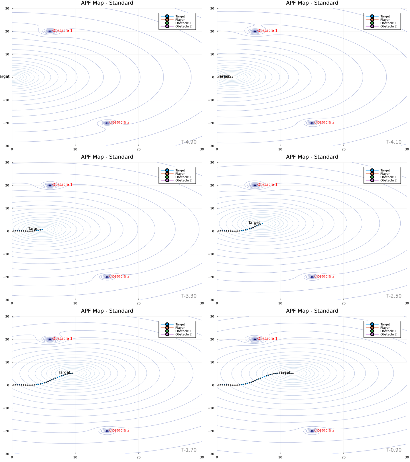
Artificial potential fields (APFs) offer an interesting approach to path planning. The use of “fake forces” makes it intuitive to combine the effects of different elements in the planning scene. However, a common a drawback is the creation of local minima, which prevent guaranteed convergence on the target.
Mathematics
The topographic height or potential of a point is denoted $\psi (\mathbf{z})$. In the standard technique,
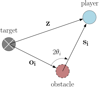
\[\psi (\mathbf{z}) = k_p \mathbf{z}^\intercal \mathbf{z} + \sum_{i=1} k_{o,i} \frac{\mathbf{z}^\intercal \mathbf{z}}{\mathbf{s_i}^\intercal \mathbf{s_i}}\]where $\mathbf{z}$ is the vector from the target to the point in space $\mathbf{z}$, while $\mathbf{s_i}$ is from the obstacle to $\mathbf{z}$.

Secant Method
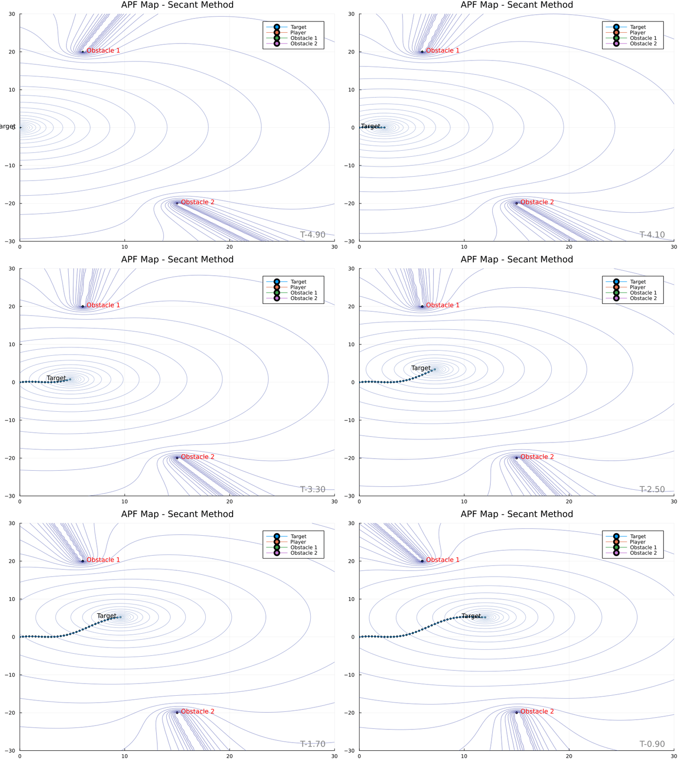
The Secant Method [1] was developed as a way to eliminate the local minimum artifact of APFs. The technique cleverly creates a potential field whose gradiant never points away from the target. Obstacles form “mountain ranges” whose peaks extend radially from the target, as opposed to circular peaks produced by the traditional technique. This is made possible by weighting the potential field with an additional factor in the range $[1, \inf)$ as a means of encoding proximity to the obstacle in a manner biased toward points where the obstacle obstructs a direct path to the target. This is achieved with a secant function having argument $\theta_i \in [0, \frac{\pi}{2})$.
\[\psi (\mathbf{z}) = k_p \mathbf{z}^\intercal \mathbf{z} + \frac{1}{2} \sum_{i=1} k_{o,i} \frac{\mathbf{z}^\intercal \mathbf{z} \sec^2(\theta_i)}{\mathbf{s_i}^\intercal \mathbf{s_i}}\]
The Secant Method yields the following potential field contour plots.

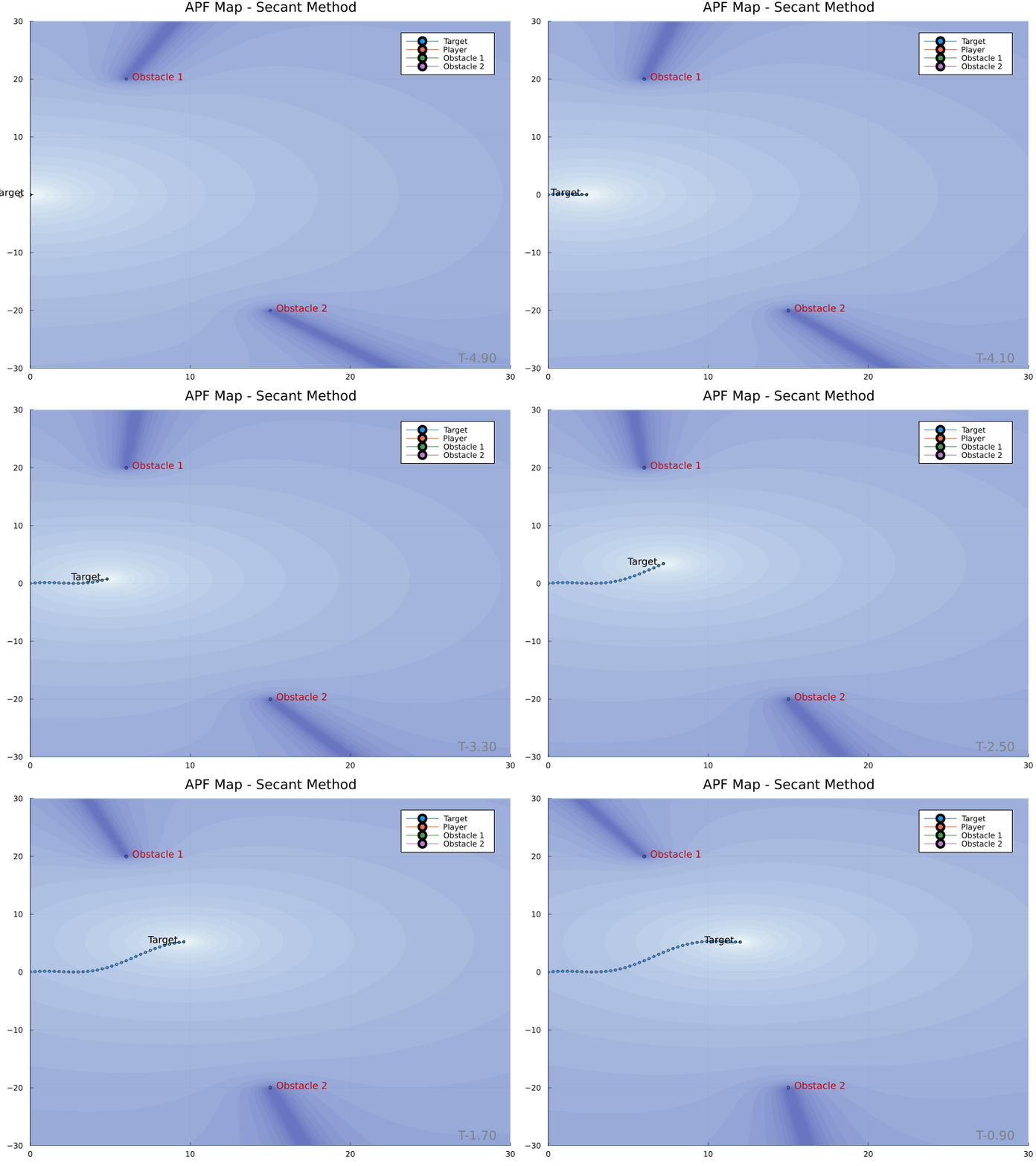
An identical map with color bars:

References
- K. J. Ahlin, N. Sadegh, and A.-P. Hu, “The Secant Method: Global Trajectory Planning With Variable Radius, Solid Obstacles,” in Volume 3: Modeling and Validation; Multi-Agent and Networked Systems; Path Planning and Motion Control; Tracking Control Systems; Unmanned Aerial Vehicles (UAVs) and Application; Unmanned Ground and Aerial Vehicles; Vibration in Mechanical Systems; Vibrations and Control of Systems; Vibrations: Modeling, Analysis, and Control, Atlanta, Georgia, USA, Sep. 2018, p. V003T32A015, doi: 10.1115/DSCC2018-9176.
